1. Introduction
This paper gives an overview of the present status of non-conventional energy sources of India, world geothermal resources, its advantages over other conventional energy sources, various uses and technologies involved in utilizing this energy source. Exploration methods used to assess the resources are explained in brief. Various geothermal provinces of India and their power generating /direct use potential are described in detail.
2. Advantages of Geothermal Energy
Geothermal energy is a domestic energy resource with cost, reliability and environmental advantages over conventional energy sources. It contributes both to energy supply,with electrical power generation and direct-heat uses.
For generation of electricity, hot water is brought from the underground reservoir to the surface through production wells, and is flashed to steam in special vessels by release of pressure. The steam is separated from the liquid and fed to a turbine engine, which turns a generator. Spent geothermal fluid is injected back into peripheral parts of the reservoir to help maintain reservoir pressure. In the absence of steam, heat from hot water is extracted through a secondary fluid and the high pressure vapour from the secondary fluid is utilized to run the turbine.
If the reservoir is to be used for direct-heat application, the geothermal water is usually fed to a heat exchanger and the heat thus extracted is used for home heating, greenhouse, vegetable drying and a wide variety of other small scale industries. Hot water at temperatures less than 120oC can be used for this purpose. Further, the spent hot water, after generating electricity can also be used for direct application.
As a result of today's geothermal production, consumption of exhaustible fossil fuels is offset, along with the release of acid-rain and greenhouse gases that are caused by fossil-fuel use. Systems for use of geothermal energy have proven to be extremely reliable and flexible. Geothermal electric power plants are on line 97% of the time, whereas nuclear plants average only 65% and coal plants only 75% on-line time. Geothermal plants are modular, and can be installed in increments as needed. Because they are modular, that can be transported conveniently to any site. Both baseline and peaking power can be generated. Construction time can be as little as 6 months for plants in the range 0.5 to 10 MW and as little as 2 years for clusters of plants totaling 250 MW or more.
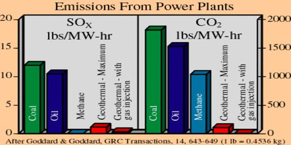
The competing goals of increased energy production for worldwide social development and of mitigating release of atmosphere-polluting gases are not compatible using today's fuel mix, which relies heavily on coal and petroleum. Development of geothermal energy has a large net positive impact on the environment compared with development of conventional energy sources.Geothermal power plants have sulphur-emissions rates that average only a few percent of those from fossil-fuel alternatives. The newest generation of geothermal power plants emits only ~135 gm of carbon (as carbon dioxide) per megawatt-hour (MW-hr) of electricity generated. This figure compares with 128 kg /MW-hr of carbon for a plant operating on natural gas (methane) and 225 kg/MW-hr of carbon for a plant using bituminous coal. Nitrogen oxide emissions are much lower in geothermal power plants than in fossil power plants. Nitrogen-oxides combine with hydrocarbon vapours in the atmosphere to produce ground-level ozone, a gas that causes adverse health effects and crop losses as well as smog. There are other environmental advantages to geothermal energy. Geothermal power plants require very little land, taking up only a fraction of that needed by other energy sources. Thus emission of CO2 and SO2 by geothermal power plants is far less compared with conventional fossil fuel based power plants (Below Figure).
Emission of CO2 and SO2 by geothermal and conventional power plants.
3. Present Status of Non-conventional Energy Resourses In INDIA:
The estimated power shortage in India in the next five years will be 43,000 MW while the total potential of non-conventional energy is about 50,000 MW. The power production status of non-conventional energy in India is shown in Table
Table Shows Power production status of non-conventional energy in India
(Chandrasekharam, 2000)
________________________________________________________________________
Renewable Power Potential Achieved
---------------------------------------------------------------------------------------------
Wind Power 20,000 MW 1,000 MW
Small Hydro Power 10,000 MW 172 MW
Biomass 20,000 MW 141 MW
Solar photo-voltaic Power 20 MW/sq.km 810 KW
Geothermal energy is not included here, although it has an estimated potential of about 10,000 MW (Ravi Shankar, 1996). The PPs (Independent Power Producers) are not aware of this potential and the country is not keen in developing this source due to the availability of 190 billion tones of recoverable coal resources which is supporting coal based power projects and hampering the healthy growth of non-conventional energy program.
Excessive use of this source without adopting strategies to mitigate its effects will have deteriorating effect on the quality of human life. In another decade emission of CO2 , SO2 and Nx will exceed 1500 million tones, 1900 kilo tones and 1200 kilo tones respectively (World Bank Report 1999). This means CO2 emissions will be 775 million metric tones per year as compared to 1000 million metric tones per year produced in the entire European Union! No doubt the cost of electricity produced from coal is far less expensive compared with other fuels. The present day cost of one unit of power is less than a rupee in the case of coal based power while liquid fuel based power costs about Rs. 2 per unit (Mehta, 1999) and hydro power costs about Rs. 1.50 (World Bank Report, 1999). But the expenditure spent to meet the consequences (like disposal of fly ash; treating the coal with high ash content etc) is high which automatically increases one rupee a unit to several rupees. The ash content in Indian coal is about 45% and the annual production of fly ash is about 75 million tons and it may cross 100 million marks very shortly. (Chandrasekharam, 2000). Only 5% of this ash is being utilized at present.
The reasons for low targets (as shown in above table) achieved through non-conventional energy sources are many. For example, solar photo-voltaic (SPV) and solar thermal are far less economically attractive than conventional technologies for, the current estimated cost of SPV modules are around $ 4 to 5 Wp (peak watt). Assuming the cost to decline by 50% in future, the estimated cost would be around $2.5Wp which is highly uncompetitive compared with $ 1.05 for other conventional sources. In the case of wind power, operational problems in matching demand and supply exists since the wind velocity is seasonal (World Bank Report, 1999). The estimated cost of power produced using geothermal resources is less than Rs. 2 /kWh (Entingh et al., 1994).
In future India has to fall in line with other countries in controlling emission of CO2, SO2 and Nx into the atmosphere and thus has to depend on cheap, environmentally clean geothermal energy resources.
4. Resources definition:
Geothermal energy, in the broad sense, is the heat in the earth and released by conduction at an average heat flux of 60 MW/m2 . The four prerequisites necessary to exploit geothermal energy are (Economides and Ungemach, 1987):
a). A heat source which could be a magma body, or a simple hot rock at depth, b) Heat carrier fluid, c) Permeable or fractured rock acting as a reservoir and d) Cap rocks providing an impermeable and insulating cover.
The most obviously usable geothermal resources require convective heat transfer i.e. presence of fluid. This occurs at a limited number of locations. When ever conduction alone prevails (any where) heat recovery requires that a fluid be forced through a large fractured heat exchange area to sweep the energy stored in the rocks at depth. This is basically the concept of hot dry rock technology, which is very promising. Hydrothermal resources are classified according to the specific enthalpy of the fluid. Waters with temperatures between 30 - 120oC are called low enthalpy resources (0.03 to 0.4MJ/kg); Waters with temperatures above 120oC are termed as high enthalpy fluids (0.5 to 3MJ/kg).
Location of geothermal provinces is dictated by the geodynamic model of the earth's crust, known as the global plate tectonics. This theory accounts for the most of the geodynamic processes affecting the earth's crust. These geodynamic processes include subduction, subsidence, uplift, fracturing etc. These occurrences result in associated geothermal features such as the distribution of heat flow, active tectonics, volcanism and hydrothermal convection.
Table Showing World Geothermal Energy Production
_________________________________________________________________
Country 1990 (MW installed) 2005 (MW installed)
---------------------------------------------------------------------------------------------------------
USA 2775 2554
Philippines 891 1931
Italy 545 790
Indonesia 145 797
Japan 215 535
New Zealand 283 445
Iceland 45 202
Costa Rica 0 163
El Salvador 95 151
China 19 28
Guatemal 0 2
Turkey 20 93
-----------------------------------------------------------------------------------------------------------
Total 5033 7691
___________________________________________________________________
5. World geothermal energy status
Currently there are an estimated 12,000 MW of direct use and over 8,000 MW of generating capacity in geothermal resources world-wide. To put geothermal generation into perspective, this generating capacity is about 0.4% of the world total installed generating capacity. The USA, Philippines, Italy, Mexico, Iceland Indonesia, Japan and New Zealand are the largest users of geothermal energy resources (both direct and indirect). Table showing the status of present electric power generation from geothermal energy in order of size per country. The 1999 capacity of 8246MW electricity was a 40% increase from the capacity installed in 1990.
Other countries with less than 20 MW generations are: Argentina, Australia Ethiopia, France (Guadeloupe), Greece, Portugal (Azores), Russia, Thailand (World Geothermal Congress, 2000). Currently geothermal resources in over 30 countries provide directly used heat capacity of over 12,000 MW. These countries include: Algeria, Austria, Belgium, Bulgaria, China, Denmark, England, France, Georgia, Germany, Greece, Hungary, Iceland, Indonesia, Ireland, Italy, Japan, Latvia, Nicaragua, Philippines, Poland, Portugal, Romania, Russia, Slovakia, Sweden, Switzerland, Thailand and Turkey.
The majority of the earlier geothermal plants were funded and operated by National Power agencies around the world with the exception of California where the development of the Geysers geothermal field was carried out by privately funded utility companies. With the recent international trend towards de-regulation in the power industry, private developers have become more directly involved in both resource assessment and development. This has been particularly so in Indonesia and the Philippines.
The world map (shown below) illustrates where geothermal resources are currently being utilised. The red dots indicate power generation which includes small scale, rural development as well as large scale power plants. Direct use is also applicable to the red dots. The blue dots indicate both high temperature and medium to low temperature resources where direct use of the geothermal heat is being applied. The yellow dots indicate World Bank funded projects, and the green dots indicate Hot Dry Rock (HDR) research is underway.
Geothermal energy utilization map of the world

Flash steam plants totally dominate the marketplace, but over the past ten years many smaller scale binary cycle plants have been installed while several combined (flash steam/binary plants) have been installed. The majority of the World's geothermal power stations are base load stations meaning that they operate 24 hours a day for 365 days. To allow for a load factor of about 80% and an average steam cost of Rs. 2 per kWh geothermal power.
6. Technology and Resource Type
Geothermal resources vary in temperature from 30-350oC, and can either be dry, mainly steam, a mixture of steam and water or just liquid water. In order to extract geothermal heat from the earth, water is the transfer medium. Naturally occurring groundwater is available for this task in most places but more recently technologies are being developed to even extract the energy from hot dry rock resources. The temperature of the resource is a major determinant of the type of technologies required to extract the heat and the uses to which it can be put. The Table 3 lists the basic technologies normally utilized according to resource temperature.
Table shows commonly used Basic technology for power generation
Reservoir Temperature
|
Reservoir Fluid |
Common Use |
Technology commonly chosen |
High Temperature >220oC |
Water or Steam |
Power Generation Direct Use |
Flash Steam; Combined (Flash and Binary) Cycle
Direct Fluid Use Heat Exchangers Heat Pumps |
Intermediate Temperature 100-220oC. |
Water |
Power Generation Direct Use |
Binary Cycle
Direct Fluid Use; Heat Exchangers ; Heat Pumps |
Low Temperature 50-150oC |
Water |
Direct Use |
Direct Fluid Use; Heat Exchangers; Heat Pumps |
7. Power Generation Technology
7.1 High Temperature Resources
High temperature geothermal reservoirs containing water and/or steam can provide steam to directly drive steam turbines and electrical generation plant. More recently developed binary power plant technologies enables more of the heat from the resource to be utilised for power generation. A combination of conventional flash and binary cycle technology is becoming increasingly popular.
High temperature resources commonly produce either steam, or a mixture of steam and water from the production wells. The steam and water is separated in a pressure vessel (Separator), with the steam piped to the power station where it drives one or more steam turbines to produce electric power. The separated geothermal water (brine) is either utilised in a binary cycle type plant to produce more power, or is disposed of back into the reservoir down deep (injection) wells. The following is a brief description of each of the technologies most commonly used to utilise high temperature resources for power generation.
Flash Steam Power Plant
This is the most common type of geothermal power plant. The illustration below shows the principal elements of this type of plant. The steam, once it has been separated from the water, is piped to the powerhouse where it is used to drive the steam turbine. The steam is condensed after leaving the turbine, creating a partial vacuum and thereby maximizing the power generated by the turbine-generator. The steam is usually condensed either in a direct contact condenser, or a heat exchanger type condenser. In a direct contact condenser the cooling water from the cooling tower is sprayed onto and mixes with the steam. The condensed steam then forms part of the cooling water circuit, and a substantial portion is subsequently evaporated and is dispersed into the atmosphere through the cooling tower. Excess cooling water called blow down is often disposed of in shallow injection wells. As an alternative to direct contact condensers shell and tube type condensers are sometimes used, as is shown in the schematic below. In this type of plant, the condensed steam does not come into contact with the cooling water, and is disposed of in injection wells.
Typically, flash condensing geothermal power plants vary in size from 5 MW to over 100 MW. Depending on the steam characteristics, gas content, pressures, and power plant design, between 6000 kg and 9000 kg of steam each hour is required to produce each MW of electrical power. Small power plants (less than 10 MW) are often called well head units as they only require the steam of one well and are located adjacent to the well on the drilling pad in order to reduce pipeline costs. Often such well head units do not have a condenser, and are called backpressure units. They are very cheap and simple to install, but are inefficient (typically 10-20 tonne per hour of steam for every MW of electricity) and can have higher environmental impacts.
Binary Cycle Power Plants
In reservoirs where temperatures are typically less than 220oC. but greater than 100oC binary cycle plants are often utilised. The illustration below shows the principal elements of this type of plant. The reservoir fluid (either steam or water or both) is passed
Binary cycle type plants are usually between 7 and 12 % efficient, depending on the temperature of the primary (geothermal) fluid. Binary Cycle plants typically vary in size from 500 kW to 10 MW. The curves in the below graph is give an indication of the electrical power output from a binary plant over a range of flows and geothermal reservoir temperatures.
Combined Cycle (Flash and Binary)
Combined Cycle power plants are a combination of conventional steam turbine technology and binary cycle technology. By combining both technologies, higher overall utilization efficiencies can be gained, as the conventional steam turbine is more efficient at generation of power from high temperature steam, and the binary cycle from the lower temperature separated water. In addition, by replacing the condenser-cooling tower cooling system in a conventional plant by a binary plant, the heat available from condensing the spent steam after it has left the steam turbine can be utilized to produce more power.
7.2 Medium Temperature Resources
Medium temperature resources are normally hot water with temperatures ranging from 100oC to 220oC. The most common technology for utilising such resources for power generation is the binary cycle technology. This technology is described above under high temperature resources.
8. Direct Use Technology
Direct use technologies are where geothermal heat is used directly rather than for power generation and are built around the extraction of heat from relatively low temperature geothermal resources, generally of less than 150oC. Because geothermal heat is non-transportable, (except short distances by fluid pipeline) any applications must generally be sited within 10 km or less of the resource.
For many resources, the relatively low temperatures and/or pressures in the reservoirs means that they have insufficient energy and/or pressure differences to naturally carry the fluids to the surface and pumps are frequently used (either down-hole or at the surface).
The type of technology selected for utilising geothermal heat for direct use applications is dependent on the nature of the geothermal fluid and the type of direct use planned. In many direct use applications, the geothermal fluid cannot be used directly, such as in drying processes or where clean steam or hot water is necessary, as geothermal fluid often contains chemical contaminants. In such cases heat exchangers are utilised to extract the heat from the hot geothermal fluid and transfer it to either clean water, or in the case of drying processes, to air.
There are two main types of heat exchangers commonly used. They are plate heat exchangers and shell and tube. The heat exchanger technology employed in the geothermal industry is the same as is commonly used over a wide range of industries where heat exchangers are utilised. Commonly used heat pump technology can also be employed in order to utilise geothermal heat for air conditioning and refrigeration applications.
9. Technological Issues with Geothermal Developments
Whether geothermal energy is utilized for power production or for direct use applications, there are issues in geothermal utilization that often have technical implications.
Geothermal fluids often contain significant quantities of gases such as hydrogen sulphide as well as dissolved chemicals and can sometimes be acidic. Because of this, corrosion, erosion and chemical deposition may be issues, which require attention at the design stage and during operation of the geothermal project. Well casings and pipelines can suffer corrosion and /or scale deposition, and turbines, especially blades can suffer damage leading to higher maintenance costs and reduced power output.
However, provided careful consideration of such potential problems is made at the design stage, there are a number of technological solutions available. Such potential problems can be normally overcome by a combination of utilising corrosion resistant materials, careful control of brine temperatures, the use of steam scrubbers and occasionally using corrosion inhibitors.
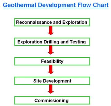
Provided such readily available solutions are employed, geothermal projects generally have a very good history of operational reliability. Geothermal power plants for example, can boast of high capacity factors (typically 85-95%) With all projects of significant size, geothermal projects are developed through a series of logical stages, which may be summarized in the Geothermal Development Flow Chart. This figure shows the various stages in a typical geothermal project. Decisions to proceed to the next stage are normally made progressively through out the project.
Reconnaissance and Exploration
Geothermal resources are usually located and defined by a progressively more intensive (and expensive) exploration programme that starts at a regional level and eventually results in a drilling program to positively delineate the resource.
Reconnaissance surveys will identify the most suitable prospect areas by recognition of favourable geological settings and locating any hot springs or other surface thermal discharge. Reconnaissance studies involve mapping any hot springs or other surface thermal features and the identification of favourable geological structures. The chemical composition of the discharging fluids reveals information about the deeper reservoir, including temperature and fluid characteristics. Geological studies provide information about the probable distribution and extent of aquifers, as well as the likely heat source and heat flow regime. Areas identified as having high potential or that are favoured because of proximity to an energy use centre, will be explored by more comprehensive scientific survey methods. In addition to more detailed geological and geochemical studies, a range of geophysical techniques may be used including gravity, magnetic and resistivity surveys. Resistivity surveys in particular can locate anomalies that are directly related to the presence of geothermal fluids. Interpretation of these integrated geoscientific studies leads to prioritisation of targets for exploration drilling programmes. The application of sound scientific method and analysis during these early phases increases the probability of success with subsequent drilling and development. If these surveys provide very good indications for the presence of a useful geothermal reservoir, the resource is tested by the drilling of exploration wells so that actual subsurface temperatures can be measured and reservoir productivity tested. The exploration programme should therefore be designed to suit the type of resource expected, the amount of energy expected to be produced from the project and the timeframe for the development.
10. Application of Chemical techniques in geothermal exploration
The application of chemical techniques has become an integral part of any geothermal exploration programme. During the pre-drilling stages of exploration, geochemistry of thermal waters and gases may provide information on deep conditions and processes not obtainable by geological or geophysical techniques. The dissolved constituents in the thermal waters can be grouped into two major groups i.e. a) Chemically, non-reactive and b) chemically reactive groups. The first group may be called tracers and the second, the geo-indicators.
The tracers, once enter the fluid phase, ideally remain unchanged, providing a tag allowing their origin to be traced back to their. These include noble gases like He and Ar and other conservative elements like Cl, Li, B, Rb, Cs and N2.
Geo-indicators are reactive species, responding to changes in their environment (especially temperature and type of rock with which the fluids interact) in a controlled and well understood manner. These include Na, K, Mg, Ca and SiO2, which take part in temperature dependent reactions with Al-silicate rocks which house geothermal systems, and H2, H2S, CH4 and CO2 which are involved in temperature -pressure dependent redox reactions within them or redox systems of the rock phase such as Fe(II)/Fe(III) reaction.
Out of the constituents mentioned above, Na, K, Mg, Ca, SiO2, Cl, Li, B, Rb and Cs enter the liquid phase while He, Ar H2, H2S, CH4 and CO2 enter the vapour phase in geothermal systems. These constituents are very useful in estimating the thermal reservoir conditions and the reservoir temperature. We shall see how these constituents are used in estimating the reservoir temperature. Those chemical constituents that are used in estimating the reservoir temperature are known as geochemical thermometers. Two such important geothermometers, the silica and cation geothermometers are discussed below. They are known as water geothermometers because they enter the liquid phase in geothermal systems.
11. Silica and Cations as geothermometers
Water geothermometers are classified into two groups i.e. 1) based on temperature dependent variations in solubility of individual minerals and 2) based on temperature dependent exchange reactions which fix the ratios of certain dissolved constituents (Fournier, 1991). The silica minerals are ideal members under group 1 while other cations such as Ca, Mg, Na and K are ideal under group 2. Temperature estimation based on group 2 members require evaluation of activity coefficients for two or more dissolved species in order to calculate the temperature at which solution-mineral equilibrium was last attained. The calculation of activity coefficients must take into account the total composition of the fluid and the result vary as a function of temperature. Simple techniques for estimating the reservoir temperatures based on silica and cations are described here.
11.1a Silica geothermometer
The solubility of silica mineral decreases drastically and linearly as temperature decreases below 340oC. If temperature vs silica concentration in thermal waters are plotted, they define a straight line within this temperature limits. Similarly the dissolved silica in liquid after steam separation (90 - 250oC) also defines a similar line. The equations for such straight lines results in the following equations:
Quartz -no steam loss to C = (1309/5.19 - log S) - 273.15 (1)
Quartz -max steam loss to C = (1522/5.75 - log S) - 273.15 (2)
The above two equations are extensively been used for calculating geothermometer temperatures in the range of 100 - 250oC. However (Fournier, 1991).
11.1b Silica- enthalpy diagram
It is useful to use enthalpy instead of temperature in the silica- temperature diagrams to estimate the reservoir temperatures. This is because, the combined heat contents (enthalpies) of two types of waters at different temperatures are conserved when they mix, and thus the dilution effect is eliminated here. Enthalpy-silica diagrams can be used to correct silica concentrations for adiabatic cooling with single stage steam loss at any temperature.
11.2 Cation geothermometers
Cation geothermometers are widely used to calculate the reservoir temperatures from surface thermal waters. This technique is based on ion exchange reactions with temperature dependent equilibrium constants. An example is the exchange of Na and K between co-existing alkali feldspars:
Na Al Si3 O8 + K = K Al Si3 O8
The equilibrium constant Keq for the above reaction is
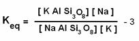
The above equation can be written as
Keq = Na / K - 4
Similar equation can be written for monovalent and divalent ions such as K and Mg, thus
Keq = K / Mg - 5
The variation of Keq with temperature can be obtained by an integrated form of van't Hoff equation
Log Keq = 1 Ho / 2.303 RT + C - 6
Where 1 Ho is the enthalpy of the reaction, T is temperature in Kelvin, R is the gas constant and C is a constant of integration.
Since 1 Ho changes little with temperature in the range of 0 to 300oC, a plot of log Na/K versus temperature will approximately be a straight line. Equations for straight line, like that developed for silica geothermometery have been proposed by several workers and two most widely used equations are given below:
Equation 5 is proposed by Fournier (1983) and 6 is proposed by Giggenbach et al., (1983). Besides these two, several other equations such as Na-K-Ca and K-Ca, Na -Ca and K- Mg have also been proposed and are in use. Giggenbach (1988) evolved a new geothermometer where both K/Na (t kn) and K/Mg (t km) geothermometers are combined. This geothermometer, represented in the form a figure by Giggenbach (1988) is wide used for the above purpose. Selecting suitable thermal water samples is very essential in estimating reservoir temperatures using geochemical thermometers.
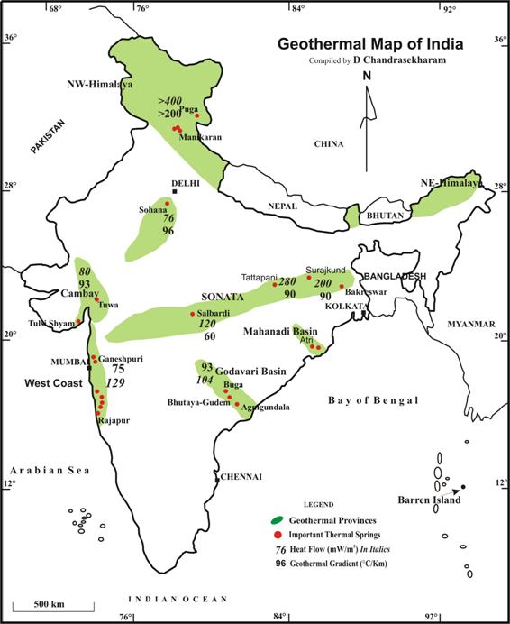
13. Indian Geothermal Provinces
In India nearly 400 thermal springs occur, distributed in seven geothermal provinces. These provinces include The Himalayas: Sohana: West coast; Cambay: Son-Narmada-Tapi (SONATA): Godavari and Mahanadi. These springs are perennial and their surface temperature range from 37 to 90o C with a cumulative surface discharge of over 1000 l/m. Figure 7 shows the location of these geothermal provinces. These provinces are associated with major rifts or subduction tectonics and registered high heat flow and high geothermal gradient (Figure 7) For example the heat flow values and thermal gradients of these provinces are 468 mW/m2; 234o C/km (Himalayas); 93 mW/m2; 70o C/km (Cambay); 120 - 260 mW/m2; 60-90o C/km (SONATA); 129 mW/m2; 59o C/km (west coast); 104 mW/m2; 60o C/km (Godavari) and 200 mW/m2; 90o C/km (Bakreswar, Bihar). The reservoir temperature estimated using the above described geothermometers are 120o C (west coast), 150o C (Tattapani) and 200o C (Cambay). The depth of the reservoir in these provinces is at a depth of about 1 to 2 km (Chandrasekharam, 2000; Minissale et al., 2000 and references therein: see web: dchandra.hypermart.net). These geothermal systems are liquid dominated and steam dominated systems prevail only in Himalayan and Tattapani geothermal provinces. The issuing temperature of water at Tattapani is 90o C; at Puga (Himalaya) is 98o C and at Tuwa (Gujarat) is 98o C. The power generating capacity of these thermal springs is about 10,000 MW (Ravi Shanker, 1996). These are, as mentioned above, medium enthalpy resources. From the point of power generation technology described above in Part I, these resources can be utilized effectively to generate power using binary cycle method. Since majority of these springs are located in rural India, these springs can support small scale industries in such areas. Dehydrated vegetables and fruits have a potential export market and India being an agricultural country, this industry is best suited for India conditions. An example of the cost involved in dehydration of fruits using conventional heat and geothermal heat, from Central America, is given in the following below table. This gives an idea about the economic potential of geothermal resource.
Table showing the cost of dehydrated fruits using conventional and geothermal heat
| Products |
Capacity(Kg) |
Time (hours) |
Heat Cost
|
Heat Cost
|
|
|
|
Geothermal Sys. |
Convential Sys. |
Pineapple |
800 |
18 |
900 |
5000 |
Apple (Slices) |
700 |
16 |
800 |
4500 |
Apple (Cubes) |
900 |
16 |
800 |
4500 |
Banana |
800 |
24 |
1300 |
6000 |
Plantain |
700 |
30 |
1500 |
6500 |
Courtesy: M/s Eco-Fruit Agro Industry,Gautimala, Central America (Cost in rupees)
Map showing Indian geothermal provinces with heat flow and geothermal gradients
Top
|